Creo Illustrate
About Creo Illustrate
Communicate complex product information effectively with rich, 3D interactive technical illustrations.
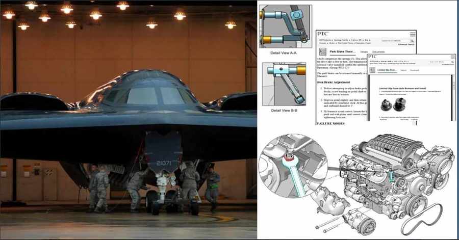
The use of 3D illustrations is a rapidly growing opportunity for manufacturers to deliver more effective technical information. Creo Illustrate couples superior 3D illustration capabilities with associative CAD data to deliver task based graphical content, specific to product configurations, supporting formats from hard copy to Augmented Reality (A/R).
Order or Request a Quote
Download Product Information
New in Creo Illustrate 10.0!
PRODUCTIVITY & USABILITY
- Model Tree
- Improved reorder and restructure workflows
- Quilt/body Evolution tree
- Improved tree display
- Productivity
- Sketcher Project/Offset
- Standard parameters and hole note for simple holes
- Pattern enhancements
- Multibody split/trim
- Surfacing
- Warp Stretch & Spine improvements
- Rotational Symmetry in Freestyle
MBD & DIGITAL THREAD
- Relating Symbols
- Relate (offset) symbols & surface finish to other annotations in MBD
- GD&T Advisor
- Usability improvements
- Improved semantic behavior for the general profile tolerance (GPT)
- Improved compliance to detailing standards
- EZ Tolerance
- Updated “New Stackup” dialog
- Undo/Redo support for components & mating features
- Improved visualization of models
SIMULATION & GENERATIVE DESIGN
- Ansys Integration
- Creo Simulation Live
- Contact Simulation and Expanded Result options
- Creo Ansys Simulation Advanced
- Non-Linear Contact and Materials
- Combined physics of Thermal and Structural
- Creo Simulation Live
- Flow and Simulate
- Creo Flow Analysis
- Improved indicator for streamline display
- Improved animation effect
- Creo Simulate
- Support for multibody parts
- Creo Flow Analysis
- Generative Design
- Rotational symmetry
- Point mass & remote loads
- Measure between regular geometry and hybrid body
ADVANCED MANUFACTURING
- Additive
- Beam Lattices
- Three new cells and Support for Auxetic cells
- Formula Driven Lattices
- Support of simulation-driven variability on FDL lattices
- New IWP cell
- Beam Lattices
- Machining
- Support for barrel tools
- Use Mill Volume for Rough and Rest-Roughing NC sequences
- New CL player for synchronized NC steps
- Step-by-step toolpath display
- Collision and gouge check
- Area Turning
- CUTCOM for each slice and Clear distance parameter
Key Benefits
Increase Comprehension and Parts Accuracy
- Clearly convey complex information: Create 3D animations to visually describe complex manufacturing and service procedures for easy consumption.
- Reduce translation costs: Replace text with illustrated step-by-step procedures, 3D animations, illustrated parts lists, and other graphical representations.
- Increase illustrator productivity
- Automate parts list creation
Accelerate Repair and Maintenance Times
- Enable easy 3D navigation of product information, based on specific product configurations and user environments.
- Provide technicians and users with easy-to-understand 3D technical information that will increase productivity and accuracy globally.
Improve Product Performance and Customer Experience
- Deliver interactive training materials and technical information to improve product adoption and customer satisfaction.
- Capitalize on growing adoption of 3D devices and applications to deliver advanced 3D product support content that is easy to find and understand.
Key Features
ILLUSTRATION TOOLS
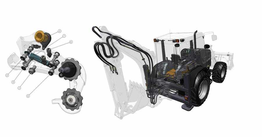
- Ability to create magnifier “inset” views in a figure to create additional detail views from a different camera viewpoint.
- Multiple explode lines to easily illustrate complex part registration.
- Lighting options that can enhance the illumination of illustrations. These include multiple light sources and the ability to adjust light levels for individual figures.
- Publish preview to review animations and sequences before publishing.
2D AND 3D PUBLISH AND EXPORT CAPABILITIES
- Add color to vector illustrations.
- Page size, border format, and figure caption.
- Publish vector illustrations from perspective or orthographic views.
- Publish all steps from a sequence to 2D or 3D formats with a single click.
SEQUENCER CAPABILITIES
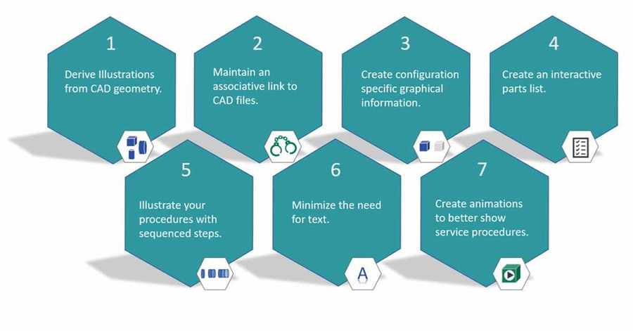
- Illustrate a procedure with sequenced steps.
- Ability to utilize 3D illustration, textual description and required resources in each step.
- Descriptions and resources automatically added from tagged symbols.
- Drag and drop to re-order steps within the sequence.
REPURPOSE CAD FOR UP-TO-DATE 3D TECHNICAL ILLUSTRATIONS AND ANIMATIONS
- Easily create 3D technical illustrations by importing design data from all major CAD systems.
- Leverage Creo® View™ ‘Adapter’ technology to quickly convert essential engineering design data, regardless of its origin, into a readily accessible format for 3D illustration.
- Interpret leading formats such as Creo and PTC CADDS ® 5, as well as other neutral formats such as STEP, IGES, VRML, and STL.
- Leverage additional CAD formats such as JT, Catia V4, I-deas, SolidWorks, and Unigraphics with adapters available for an additional cost.
GENERATE ILLUSTRATED PARTS LISTS AND CALL OUTS
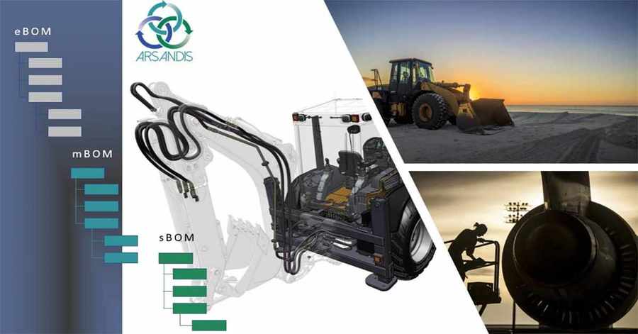
- Create an interactive parts list that reflects the structure of the sBOM, representing the entire Bill of Materials or a subset.
- Repurpose engineering CAD metadata to produce dynamic parts list information quickly and accurately.
- Generate and apply call outs from parts lists automatically.
- Customize call out styles quickly and easily.
- Publish illustrated parts lists quickly using Arbortext® Service Information Solutions, Arbortext® Editor™ or your own custom delivery application based on PTC Creo View Express.
CREATE 3D ANIMATIONS FOR INTERACTIVE TECHNICAL INFORMATION
- Create, capture, and play back detailed 3D animation sequences. Events recorded in the timeline can be edited, duplicated, or reversed.
- Augment animation with notes, symbols, and tools from a standard or custom library.
- Insert 3D notes with warnings or instructions related to the task being described in the animation.
ILLUSTRATE MULTIPLE FIGURES IN A SINGLE ILLUSTRATION FILE
- Author multiple figures per illustration file, repurposing the same model geometry in each figure.
- Automatically capture sBOM structure, part visibility, camera orientation, render style, and additional notations for each figure.
- Create new figures from scratch or duplicate a previous static or animated figure.
ILLUSTRATE DYNAMIC SECTIONING TO PRESENT INTERNAL ASSEMBLY COMPONENTS
- Section components on a single plane or quarter-cut to produce dynamic section views of a CAD model.
- Leverage section views within 3D technical illustrations or record within an animation.
- Apply sections to the entire model or, for more complex designs, to a subset of components.
REPURPOSE 3D ILLUSTRATION INTELLIGENCE WITHIN HIGH-QUALITY ARBORTEXT® ISODRAW® CADPROCESS™ 2D ILLUSTRATIONS
- Reuse Creo Illustrate output in Arbortext IsoDraw CADprocess to support all 2D service information deliverables.
- Save entire 3D illustrations or a single step of an animation.
- Leverage 3D intelligence to easily create additional 2D call outs in the proper sequence.
AUTOMATE ILLUSTRATION CHANGE MANAGEMENT THROUGHOUT THE PRODUCT LIFECYCLE
- Maintain associativity with engineering data to automate change processes when design changes occur throughout the product lifecycle.
- Integrate with Windchill, Creo, and Arbortext products to enable enterprise-wide delivery of 3D service and parts information.
Insights: 3D Illustrations with PTC Creo Illustrate
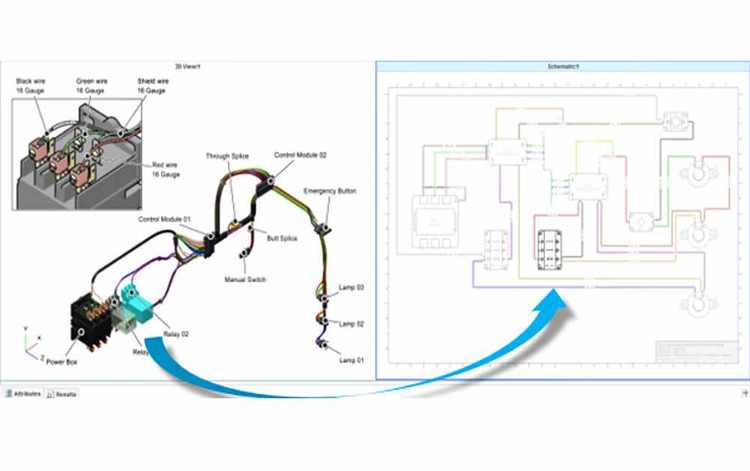
Creo Illustrate Schematics
2D charting software for creating 2D schematic diagrams of wiring and cable systems.
- Interactive schematics with cross selection highlighting.
- Application of color based on desired interpretation of data.
- Associativity with source engineering data.
- Cross-linkage between Models of the same System.
Re-purpose schematic diagrams to enhance interactive trouble shooting!
Project References
HIROTEC AMERICA


